Ford Cam Synchronizer Sensor Wiring Diagram
In this Arduino Tutorial we will learn how the HC-SR04 Ultrasonic Sensor works and how to use it with the Arduino Board. You can watch the following video or read the written tutorial below.
How the HC-SR04 Ultrasonic Sensor Works
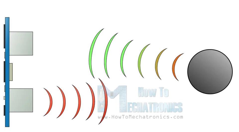
It emits an ultrasound at 40 000 Hz which travels through the air and if there is an object or obstacle on its path It will bounce back to the module. Considering the travel time and the speed of the sound you can calculate the distance.
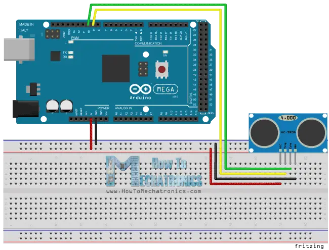
The HC-SR04 Ultrasonic Module has 4 pins, Ground, VCC, Trig and Echo. The Ground and the VCC pins of the module needs to be connected to the Ground and the 5 volts pins on the Arduino Board respectively and the trig and echo pins to any Digital I/O pin on the Arduino Board.
Components needed for this tutorial
You can get these components from any of the sites below:
- Ultrasonic Sensor HC-SR04 …………Amazon / Banggood / AliExpress
- Arduino Board …………………………… Amazon / Banggood / AliExpress
- Breadboard and Jump Wires ………Amazon / Banggood / AliExpress
Disclosure: These are affiliate links. As an Amazon Associate I earn from qualifying purchases.
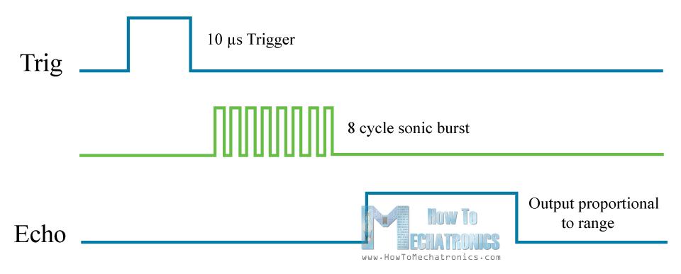
In order to generate the ultrasound you need to set the Trig on a High State for 10 µs. That will send out an 8 cycle ultrasonic burst which will travel at the speed of sound and it will be received in the Echo pin. The Echo pin will output the time in microseconds the sound wave traveled.
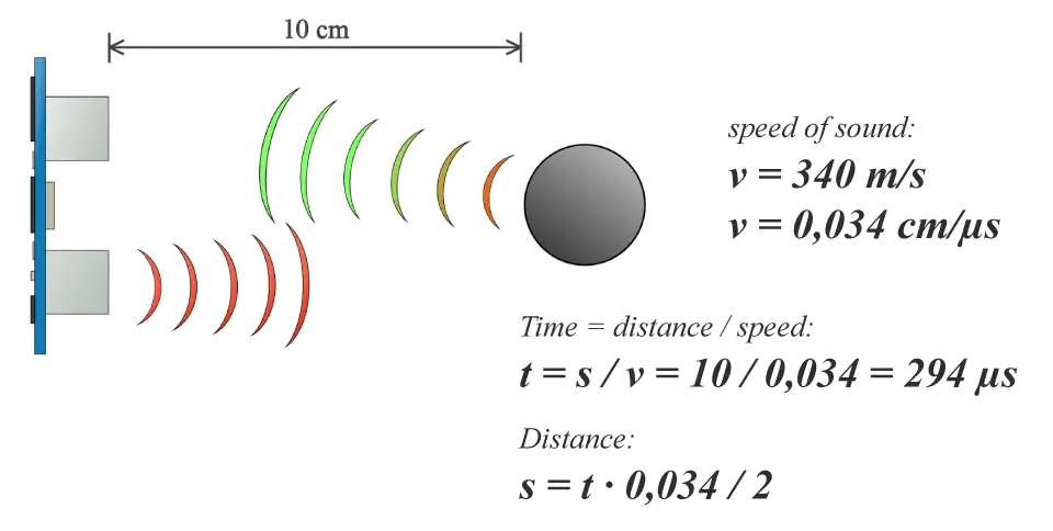
For example, if the object is 10 cm away from the sensor, and the speed of the sound is 340 m/s or 0.034 cm/µs the sound wave will need to travel about 294 u seconds. But what you will get from the Echo pin will be double that number because the sound wave needs to travel forward and bounce backward. So in order to get the distance in cm we need to multiply the received travel time value from the echo pin by 0.034 and divide it by 2.
Arduino and HC-SR04 Ultrasonic Sensor Code
First you have to define the Trig and Echo pins. In this case they are the pins number 9 and 10 on the Arduino Board and they are named trigPin and echoPin. Then you need a Long variable, named "duration" for the travel time that you will get from the sensor and an integer variable for the distance.
// defines pins numbers const int trigPin = 9; const int echoPin = 10; // defines variables long duration; int distance;
In the setup you have to define the trigPin as an output and the echoPin as an Input and also start the serial communication for showing the results on the serial monitor.
void setup() { pinMode(trigPin, OUTPUT); // Sets the trigPin as an Output pinMode(echoPin, INPUT); // Sets the echoPin as an Input Serial.begin(9600); // Starts the serial communication } In the loop first you have to make sure that the trigPin is clear so you have to set that pin on a LOW State for just 2 µs. Now for generating the Ultra sound wave we have to set the trigPin on HIGH State for 10 µs. Using the pulseIn() function you have to read the travel time and put that value into the variable "duration". This function has 2 parameters, the first one is the name of the echo pin and for the second one you can write either HIGH or LOW.
// Clears the trigPin digitalWrite(trigPin, LOW); delayMicroseconds(2); // Sets the trigPin on HIGH state for 10 micro seconds digitalWrite(trigPin, HIGH); delayMicroseconds(10); digitalWrite(trigPin, LOW);
In this case, HIGH means that the pulsIn() function will wait for the pin to go HIGH caused by the bounced sound wave and it will start timing, then it will wait for the pin to go LOW when the sound wave will end which will stop the timing. At the end the function will return the length of the pulse in microseconds.
For getting the distance we will multiply the duration by 0.034 and divide it by 2 as we explained this equation previously.
// Reads the echoPin, returns the sound wave travel time in microseconds duration = pulseIn(echoPin, HIGH); // Calculating the distance distance= duration*0.034/2; // Prints the distance on the Serial Monitor Serial.print("Distance: "); Serial.println(distance); At the end we will print the value of the distance on the Serial Monitor.
Here's the complete code:
/* * Ultrasonic Sensor HC-SR04 and Arduino Tutorial * * by Dejan Nedelkovski, * www.HowToMechatronics.com * */ // defines pins numbers const int trigPin = 9; const int echoPin = 10; // defines variables long duration; int distance; void setup() { pinMode(trigPin, OUTPUT); // Sets the trigPin as an Output pinMode(echoPin, INPUT); // Sets the echoPin as an Input Serial.begin(9600); // Starts the serial communication } void loop() { // Clears the trigPin digitalWrite(trigPin, LOW); delayMicroseconds(2); // Sets the trigPin on HIGH state for 10 micro seconds digitalWrite(trigPin, HIGH); delayMicroseconds(10); digitalWrite(trigPin, LOW); // Reads the echoPin, returns the sound wave travel time in microseconds duration = pulseIn(echoPin, HIGH); // Calculating the distance distance= duration*0.034/2; // Prints the distance on the Serial Monitor Serial.print("Distance: "); Serial.println(distance); } See also: Arduino Range Measurer and Digital Spirit Level Project
Arduino Ultrasonic Sensor and LCD Display Example
Here's another example how to use the ultrasonic sensor with Arduino and display the results on an LCD.
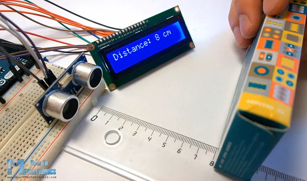
You can connect the ultrasonic sensor and the LDC as following:
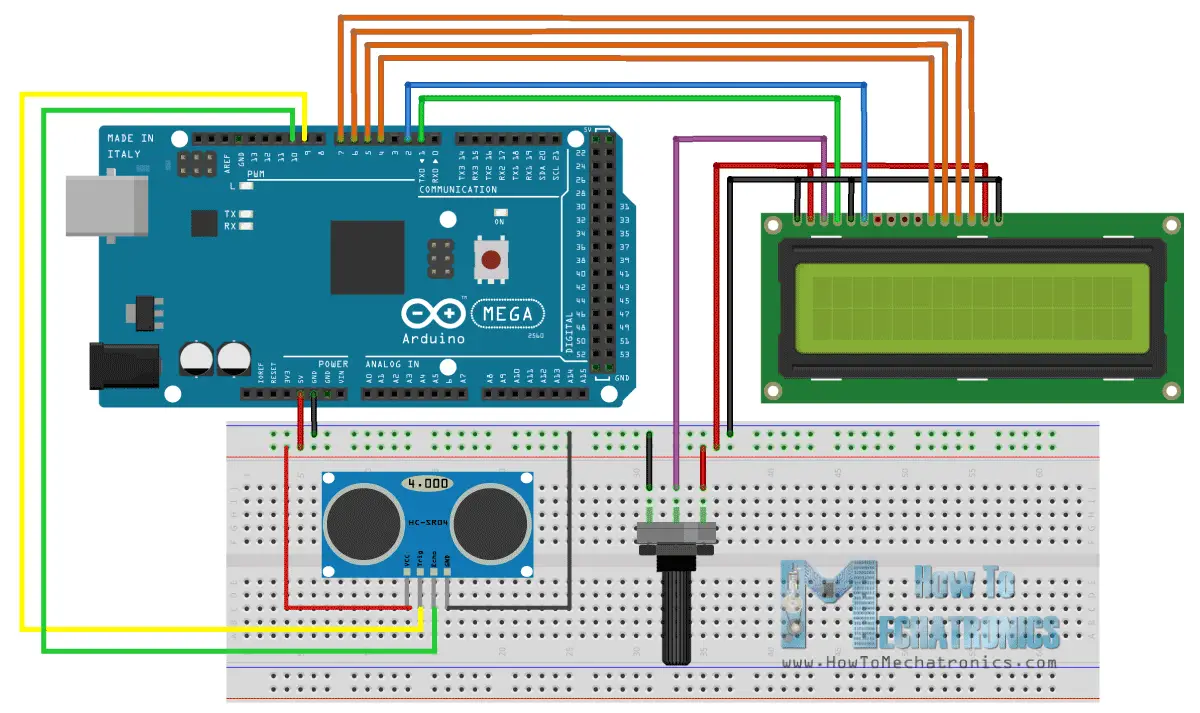
The code measuring the distance is pretty much the same as the basic example. Here, instead of printing the results on the serial monitor we print them on the LCD. If you need more details how to use and connect an LCD with Arduino you can check my particular tutorial for it.
/* * Ultrasonic Sensor HC-SR04 and Arduino Tutorial * * by Dejan Nedelkovski, * www.HowToMechatronics.com * */ #include <LiquidCrystal.h> // includes the LiquidCrystal Library LiquidCrystal lcd(1, 2, 4, 5, 6, 7); // Creates an LCD object. Parameters: (rs, enable, d4, d5, d6, d7) const int trigPin = 9; const int echoPin = 10; long duration; int distanceCm, distanceInch; void setup() { lcd.begin(16,2); // Initializes the interface to the LCD screen, and specifies the dimensions (width and height) of the display pinMode(trigPin, OUTPUT); pinMode(echoPin, INPUT); } void loop() { digitalWrite(trigPin, LOW); delayMicroseconds(2); digitalWrite(trigPin, HIGH); delayMicroseconds(10); digitalWrite(trigPin, LOW); duration = pulseIn(echoPin, HIGH); distanceCm= duration*0.034/2; distanceInch = duration*0.0133/2; lcd.setCursor(0,0); // Sets the location at which subsequent text written to the LCD will be displayed lcd.print("Distance: "); // Prints string "Distance" on the LCD lcd.print(distanceCm); // Prints the distance value from the sensor lcd.print(" cm"); delay(10); lcd.setCursor(0,1); lcd.print("Distance: "); lcd.print(distanceInch); lcd.print(" inch"); delay(10); } I hope you enjoyed this tutorial and learned something new. Feel free to ask any question in the comments section below and don't forget to check out my collection of Arduino Projects.
Source: https://howtomechatronics.com/tutorials/arduino/ultrasonic-sensor-hc-sr04/
Posted by: vannessaforrinftort0.blogspot.com

Posting Komentar untuk "Ford Cam Synchronizer Sensor Wiring Diagram"